This circuit can be used to automatically control the light of your porch or the terrace. The light switches on as soon as it gets dark and after everyone in the house goes to bed then the light switches off by itself. 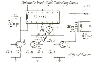 The circuit is designed by tow LDR controlled switches and a relay circuit driven by a single gate. LDR-1 senses the sunlight outside of the house while LDR-2 is used to sense the light inside the house. Both the transistors Tl and T2 conduct only when both the LDRs remain in light. At this stage the collector voltages of the two transistors remains low but when both the LDRs are in the dark then Tl and T2 remain cut off and their collectors are in the high state. Output from the two collectors is the input to the X-OR Gate. When any one transistor is in cut off state while the other one is conducting then the input to the X-OR gate. When any one transistor is in cut off state while the other one is conducting then the input to the X-OR gate is 1, 0 or reverse of it. Output of the X-OR gate remains high in both of these cases and it keeps the transistors T3 and T4 cut off. In this situation the relay is also kept off. A 2-Pole, 2-way relay is used here and wiring of the relay switches is done in a manner to switch on the low light.
When both the LDRs are either in the dark or when both are in the light then the input to the X-OR gate is 0, 0 or 1, 1. The output of the X-OR gate remains "1" in both of these cases. As a result T3 and T4 part conducting and the relay is switched ON to turn the light OFF. Care should be taken to place the LDRs in proper locations.

When both the LDRs are either in the dark or when both are in the light then the input to the X-OR gate is 0, 0 or 1, 1. The output of the X-OR gate remains "1" in both of these cases. As a result T3 and T4 part conducting and the relay is switched ON to turn the light OFF. Care should be taken to place the LDRs in proper locations.
Comments
Post a Comment